

A simple design for a pair of one-meter coils consists of ten turns each of #10 AWG copper wire housed in wooden boxes. Combined coil resistance is 1Ω.
Per IEC 61000-4-8 Power Frequency Magnetic Field Immunity Testing;
H=1.22 (N/D) * I A/m
For the GME coils; H=12.2 * I A/m,
When the coils are connected to the power resistor, the system impedance is 4 Ω
| Magnetic Field (A/m) | Coil Current (I) | Coil Voltage (V) |
|---|---|---|
| 3 | 0.25 | 1 |
| 10 | 0.8 | 3.3 |
| 30 | 2.5 | 10 |
| 100 | 8.2 | 33 |
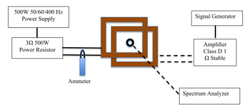
The Helmholtz coils can also be used for magnetic field immunity testing from 30 Hz to 150 kHz. (Dotted Lines)
A signal generator is connected to a power amplifier, and the output of the amplifier is connected to the coils.
A spectrum analyzer is connected to a loop antenna that is placed in the coils. The signal generator is swept over the frequency range and the field is verified on the spectrum analyzer display.
Reference: MIL-STD-461 RS101
