Method of Testing Conducted Emissions on Maritime Equipment
Method of Testing Conducted Emissions on Maritime Equipment:
I. Applicable Standards
The unit was evaluated for compliance with International Standard IEC 60945 Ed. 4, "Maritime Navigation and Radiocommunication Equipment and Systems – General Requirements – Methods of Testing and Required Test Results (August 2002, and A1 2008)."
II. Measuring Equipment
The table below describes the instrumentation used by Green Mountain Electromagnetics to perform this testing:

III. Measurement Procedure
Conducted Emissions in accordance with IEC 60945, Para. 9.2.
Frequency range: 10 kHz to 150 kHz
Limit: 96 dBuV decreasing to 50 dBuV
Frequency range: 150 kHz to 350 kHz
Limit: 60 dBuV decreasing to 50 dBuV
Frequency range: 0.35 MHz to 30 MHz
Limit: 50 dBuV
a. Set up instrumentation in laboratory.
i. Mount EUT on ground plane.
ii. Observe temperature, humidity and atmospheric pressure.
iii. Attach EUT power cable to the Artificial Mains V-Network/Line Impedance Stabilization Network (AMN/LISN).
b. Verify spectrum analyzer and AMN/LISN operation.
i. Spectrum analyzer is connected to AMN/LISN.
ii. Measurements are made at both phase (L1/+DC) and neutral (L2/-DC) leads.
c. Set up, power and operate EUT as described in Section V.
i. Use shielded power cable not to exceed 0.8 m in length.
d. Perform preliminary evaluation of equipment.
i. Vary EUT modes.
ii. Repeat step d.i. while evaluating conducted emissions from 10 kHz to 30 MHz.
iii. Ensure resolution bandwidth is set and less than or equal to video bandwidth.
e. Determine frequencies that produce maximum emissions.
i. Identify beat frequencies and harmonics.
f. Perform final evaluation of unit by recording spectrum analyzer data.
i. Ensure the EUT is producing the maximum emissions found in step e.
ii. Collect data over the entire frequency range.
IV. Conducted Emissions Data
The following page contains the spectrum analyzer output from the testing. Limits superimposed on the data are corrected for transducer and measurement system gain or loss. Correction factors at selected frequencies are shown below:
Corrected Limit (dBuV) = Limit (dBuV) – LISN Insertion Loss (dB).

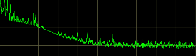
IV. Conducted Emissions Data Continued
Maritime Conducted Emissions at GME
· Reduce emissions by adding 1 uF capacitor DC +/- to ground plane –
6 dB under at 236 kHz